Purdue Electric Racing Hardware Work
Traction Control Board Version 1.0
In preparation for a hub motor car with torque vectoring control, in fall 2019 along with the electronics and drivetrain subteams I helped to start research into vehicle control systems. Taking from prior experience working on systems where too many variables were at play, I set out to develop a platform where we could approach a total vehicle controls system in smaller chunks, and also create hardware which would allow us to gather the important data we needed to make controls decisions. Traction / launch control was seen as a logical starting place for our application because it used a lot of the same data that the final torque vectoring system would use, at a much lower complexity on the side of the controller. This gave us fewer parameters to tune and would make it easier to learn what works and what doesn't when adjusting the system to our car. This board takes three different measurements; a wheel speed measurement from wheel speed encoders, a strain measurement from a strain gauge on the push rod, and a position measurement using a linear potentiometer on our suspension springs. The wheel speed measurement gives us an idea of our speed but can also help us detect slip events when uncharacteristic acceleration / deceleration is detected. The strain and position measurements work together to predict the normal force on our tires. With these measurements we can make predictions about the grip that is available to us and also record data on under what conditions we are slipping so that future traction loss can be prevented. While our control software has not been tested given the pandemic, below is a block diagram which describes its basic function. Using the normal force data, predictions can be made about the grip available and set a limit on the torque being sent to the wheels. Then a standard feedback controller modulates this torque based on received data to either move closer to the setpoint from the driver input, or scale back further under slip. The controller is designed with the feedforward portion to react quickly but with conservative estimates so that car performance is not negatively impacted. It was important to distinguish under what conditions we believed slip was sure to happen and characterize uncertainty that the feedback based controller would be more suited to deal with. The hardware of the traction control board is designed to be simple and accurate in order to be reliable but also to limit the amount of steps in between data being created and data being interpreted. Each board connects to the vehicle's CAN bus and is designed to be packaged in heat shrink tubing and be velcro or zip tied in place. Its compact design and slender shape allows flexibility in placement, and also reduces packaging overhead.
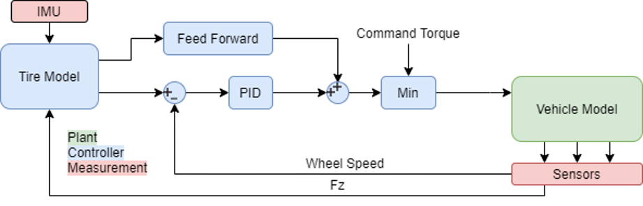
Traction controller block diagram
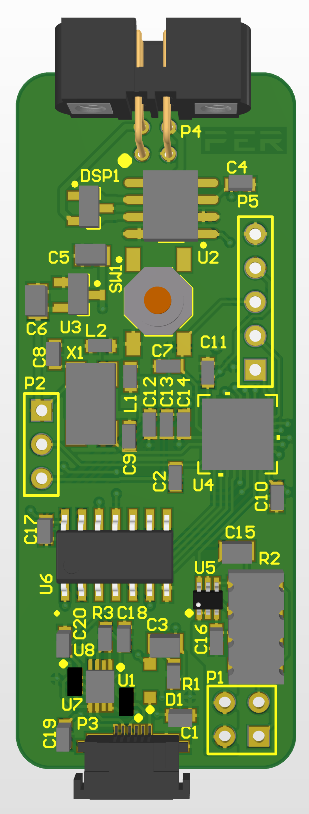
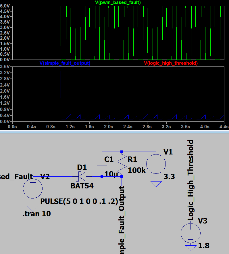
Left: Traction control board assembly in Altium Right: Fault simplification circuit simulation. The encoder registers faults as different PWM duty cycle signals, but for these purposes every fault is seen the same. This circuit simplifies a PWM signal into a low and lets a no fault signal (high) pass through. It also level shifts the no fault signal to the microcontroller voltage.
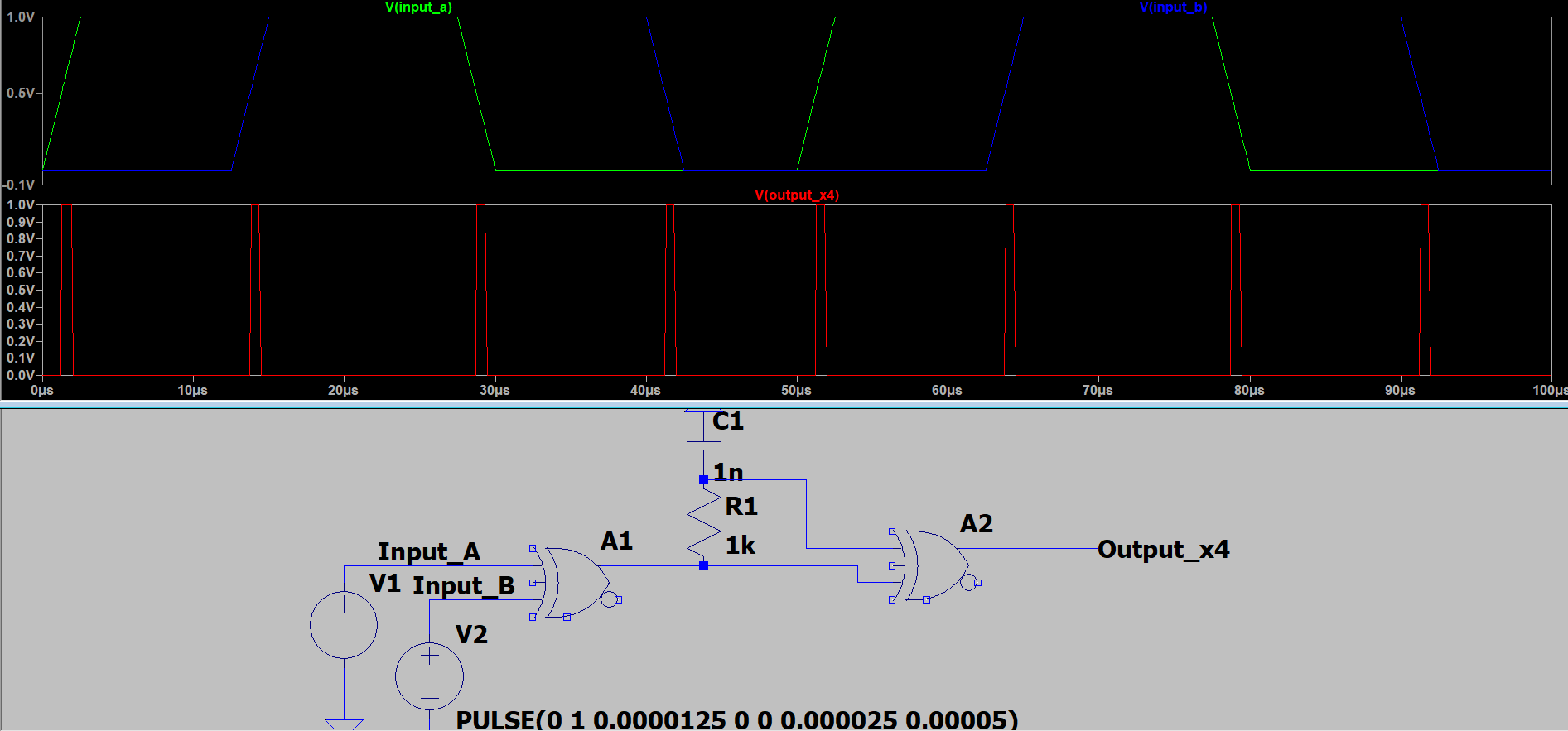
Demonstration of encoder input circuit with 90° phase shifted inputs and edge detection for x4 resolution output. Allows for quicker data input at very low vehicle speeds